
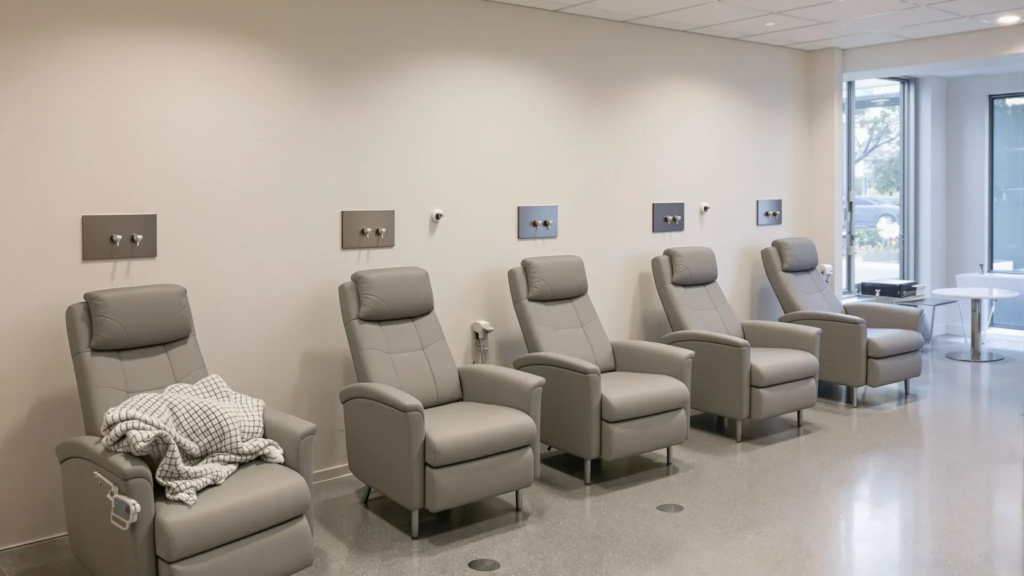
A dialysis unit is designed around the water that reaches every chair. Each patient sits in a recliner for three to six hours, up to three days a week, connected to a machine that needs treated water and a drain for the whole session. So the plan starts with the water treatment plant room and the loop of pipe that runs from it past every chair and back.
In most medical fitouts in a commercial building, water only has to reach a few basins and a toilet. A satellite dialysis unit can sit away from a hospital, in a community health centre or another building, and the Australasian Health Facility Guidelines (AusHFG) prefer a central water plant once a unit has six chairs or more. We place the plant room, the pipe route and the floor wastes on the plan before we place a chair.
Chair Bays and the Services Wall Behind Them
Each dialysis chair bay is planned at about 9 square metres, a 3 metre square. Bays are grouped in pods of 4 to 6 chairs or set around one central station, with a hand basin for every four open bays and at least one enclosed 12 square metre room for patients who need to be kept apart. Patients spend long hours in the chair, so the bays need daylight and an outside view, and because many units run an evening shift, the window coverings also have to give privacy after dark.
On an office floor we can set the chairs in a row facing the windows, with their services on a new wall behind them. That wall carries the medical services panel, with oxygen, suction, emergency power outlets and nurse call buttons, backed in the frame the same way as the panels in a day procedure unit's recovery bays. Beside it sits the dialysis wall box, which is recessed into the wall and sets how the wall is built.
The Wall Box, Tundish and Drain at Each Chair
The wall box has two connections, one for treated water and one for the machine's drain. Below them is a tundish, a small open funnel the drain water falls into across an air gap, so waste cannot siphon back up the line. The tundish has a viewing panel so staff can see the water leaving, and its outlet drops straight into the drain pipe so waste does not run over the inside of the box.
Both lines use quick-connect fittings. They are chosen so a machine cannot be coupled to an ordinary water outlet, and keyed so the supply and drain lines cannot be swapped.
Each machine also flushes 1 to 2 litres of hot water to drain when it heat-cleans itself, so the hydraulic designer may specify a larger trap at each point to mix it with cold water. The drain pipe is a chemically resistant plastic such as high-density polyethylene, and where drains run behind a cover or screen, the cover has to be ventilated, because a sealed enclosure lets condensation build up and mould grow.
The hydraulic contractor supplies and connects the box, the tundish and the pipework, and we build the wall around them. We frame the opening at the height on the hydraulic drawings, add backing for the box and the services panel, and keep the wall unsheeted until the plumber has tested the water and drain lines. Each bay also gets an access panel so the trap can be reached without cutting the wall, and a full-height protection panel behind the chair.
The Treated Water Loop from Plant Room to Chairs
Treated water leaves the plant room in a continuous loop that passes every wall box and returns to the plant, with no dead ends or branches where water can sit still. The loop is kept under about 200 metres where feasible, which is easier when the plant room sits beside the treatment area and the chairs run in rows along one or two walls.
The loop is a specialist plastic or polished stainless steel pipe, with no copper or brass anywhere after the water enters the plant room, and it is heat-sanitised regularly with water returning at 80 to 90 degrees. It carries at least 25 millimetres of insulation, so it takes more room in the ceiling void and inside the wall than an ordinary water pipe.
Behind a row of chairs, we can build the services wall with plasterboard partitions on a steel stud frame, giving it a wider cavity than a standard office wall so the recessed boxes, the insulated loop and the drains all fit inside. We confirm the stud size against the wall box and pipe drawings before framing, because changing it later means taking the wall down.
Above the chairs, a suspended ceiling with drop-in acoustic tiles keeps the loop within reach. If biofilm or corrosion ever sets in, the loop may need replacing, so we can keep it out of fixed plaster bulkheads and reachable along its whole run.
Floor Wastes Across the Treatment Floor
Every treatment and maintenance area needs floor wastes, because a disconnected line can put a large volume of water on the floor in a short time. Neighbouring bays can share a floor waste for spills, with the sheet vinyl clamped into each waste under a ring so the grate sits flush. The vinyl is slip resistant, coved up the walls and chosen to take years of contact with acid and alkaline solutions.
On a ground-floor slab, a new floor waste can mean cutting a trench for the pipe to reach the drainage connection. On an upper floor, each waste is a core hole through the slab with its pipe running under the slab in the tenancy below, so the positions are fixed early and agreed with the landlord. Office buildings usually want the structural engineer's written approval before any coring, and many do not allow core drilling during business hours, so we schedule it for nights or weekends.
The weigh bay belongs on the same floor plan. Patients weigh in and out at every session, and where the unit wants a platform scale set flush into the floor for wheelchair users, the recess is set out with the floor wastes before the vinyl goes down.
The Water Treatment Plant Room
The plant room holds the particle filters, a water softener and brine tank, carbon filters, an ultraviolet unit and the reverse osmosis (RO) plant, which pushes water through a membrane to strip out salts, metals and bacteria. The room is planned at about 18 square metres in a unit of up to 12 chairs and 22 square metres for up to 24, with the final layout set by the equipment the renal service buys.
The room sits beside the treatment area, because nurses check the plant several times a day, and on the edge of the unit with a second door for deliveries of salt, filter media and replacement equipment. Both doorways are planned at 1,600 millimetres clear, with a main leaf and a half leaf, so a pallet jack can get through.
Softeners, carbon filters, salt and the RO plant are heavy, so a structural engineer assesses the floor before the plant position is fixed. The room has no windows, its ceiling is flush-set moisture-resistant plasterboard and its floor is sealed concrete with a coved concrete skirting.
A floor waste and a larger sump waste take high flows and water up to 90 degrees, because the plant sends very hot water to drain after each heat-cleaning cycle. The hydraulic designer adds cooling for that water, such as a cooling pit or cold-water injection, before it reaches the building's drainage.
The room runs 24 hours a day, and its noise has to be kept away from the chairs. We run its walls through the ceiling line to the slab above and fill the cavity with insulation, because sound crosses the ceiling void over any wall that stops short. The doors are solid core with acoustic seals, since a door is usually the weakest part of a wall for sound.
Where the plan allows, we can also place the store or the workroom between the plant room and the chairs as a buffer. The equipment gives off a lot of heat but only runs reliably between 5 and 30 degrees, so the room's air-conditioning is connected to the building management system, with an alarm if the temperature climbs and spare cooling capacity. If the building's air-conditioning runs only in business hours, the room needs its own unit, much like a server room in an office fitout.
Bulk Store, Technical Workroom and the Delivery Route
Dialysis fluids and consumables arrive on pallets on a regular basis, so the bulk store goes on the edge of the unit where a pallet lifter can reach it. It is usually planned at about 18 square metres for a 10-chair unit, with heavy-duty shelving that carries 100 kilograms and shelves at least 400 millimetres apart or adjustable. As with an office storage room, the size comes from the shelving bays and the aisle between them, and here the aisle has to take a pallet lifter.
Pallets come off a truck, along a corridor and through the store door, so the delivery route sets the door clearances along the way, and a roller door may be needed on the store itself. Above the ground floor the goods lift has to take a pallet lifter, so we check the lift car on the first site visit, and the floor where pallets land needs a heavy-duty finish.
The technical workroom, where renal technicians service the machines and spare machines are kept, also sits on the edge of the unit. Every machine position in it needs power and a water and drain connection, even for a spare machine in storage. It is usually planned at about 12 square metres for a 10-chair unit, plus 1.5 square metres for each extra station.
The dirty utility needs a porcelain disposal unit, because spent dialysate concentrate corrodes stainless steel. The waste disposal room sits on the outside edge of the unit and locks, so waste can be collected after hours. The clean store, medication room and staff room are built much as in other clinical units.
Emergency Power and the Order We Build In
Emergency power is usually considered for the patient areas and the plant room, with an uninterruptible power supply often suggested for the machine circuits and the RO plant controls, segregated in line with AS/NZS 3003, the wiring standard for patient areas. The standard plant room layout has eight double emergency power outlets at high level. In a commercial building the electrical engineer works out early how all of that connects to the building's own supply and switchboard.
On site, core holes and floor wastes go in first, then the plant room walls and the framing for the bays, with backing for wall boxes, services panels and protection panels. The loop, drains, medical gases, power and data run through the ceiling void and the open walls. Once the plumber has tested the loop and drains, the walls are sheeted, the vinyl goes down and the boxes, panels and outlets are fitted off, leaving the plant room ready for the equipment the water treatment specialist supplies.
We can build a dialysis unit around its water, starting with the plant room and the floor wastes and finishing with a tested outlet and drain at every chair.
📞 Call us on 1300 60 93 93