
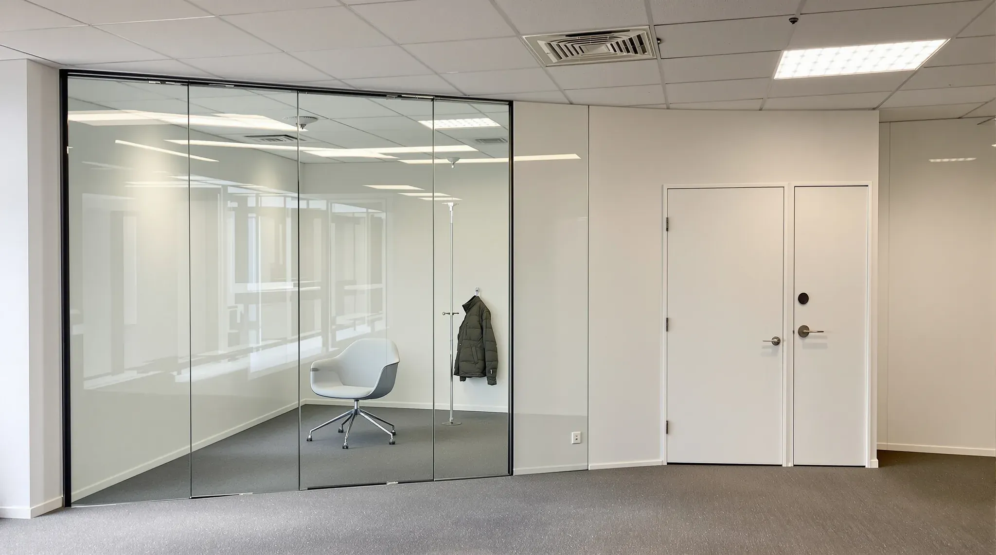
A fitout site measure settles whether a partition layout can be built where it is drawn, and what each wall will cost to build there. Heights to the slab, the ceiling grid, window mullions, columns, floor levels and the services above the ceiling all change how each wall is built, and we check every one on the floor itself because base building drawings do not always show what earlier fitouts changed.
When we measure a floor for office partitions, we walk every proposed wall line from end to end, take heights at several points, lift ceiling tiles along the way and photograph what we find. We can do that walk with the interior designer or architect before the layout is fixed, and the readings come back on a marked-up plan, so a wall that has to shift moves on paper before it is priced.
Heights Along Each Wall Line
At each reading point we record three heights. The first is the floor to the underside of the concrete slab above (the soffit), which is the height a slab-to-slab wall is built to. The second is the floor to the underside of the existing ceiling, and the third is the depth of the ceiling void between the two.
We take them at both ends of a wall line, at its middle and wherever a beam crosses it, because a beam hangs lower than the slab around it and a ceiling is not always at one level across a floor. Under each line we also note what fills the void and how low it hangs, including ducts, cable trays, sprinkler mains and pipes.
A wall taken to the slab is framed around every one of those services and sealed where each one passes through. When a wall stops at the ceiling with an insulation or plasterboard barrier in the void above it, the barrier is fitted around the same services. The readings show whether each wall can be taken through the ceiling to the slab or stops at the ceiling with a barrier over it.
The tallest reading on a line also sets the stud. Each steel stud size reaches only a certain height at a given spacing and lining, so a wall line that measures taller than the base building drawings show is framed and priced from the measured figure.
Columns, the Ceiling Grid and the Window Line
Columns are measured to their finished face, cladding included, and tied back to the building core and the facade. A wall that meets a column is set out from that face. Where a proposed wall would sit just off a column face, we note the gap, because a sliver of wall that narrow is hard to frame and line. Thermostats, outlets and anything else fixed to a column go on the plan as well.
In a suspended ceiling we record the grid module, commonly 1200 by 600 or 600 by 600 millimetres, the direction of the main runners hung from the slab, and where the grid lines fall against each proposed wall. A wall built to the ceiling has its head track fixed along the grid, so a wall line partway across a row of tiles leaves cut tiles on both sides. Shifting that wall onto the nearest grid line, where the room allows, keeps the tiles whole.
At the facade we measure the centre of each window mullion, the vertical bar between panes of glass, along with the sill and window head heights, any blind pockets at the ceiling and any air conditioning units standing on the floor along the perimeter. Each wall that runs to the facade has to land on a window mullion, so the mullion centres set the widths of rooms along the glass. A perimeter unit under the sill decides where a wall end can stop.
Services in the Ceiling Above Each Wall
Along each wall line we mark every ceiling fitting near the wall, including sprinkler heads, smoke detectors, supply diffusers, return air grilles, light fittings and exit signs. A light fitting or diffuser that straddles the line is moved before the wall goes in, and an exit sign that a new wall would hide is relocated or another one added.
A new room enclosed from open floor usually needs a sprinkler head and a smoke detector of its own, and a head left close to a new wall may need to move. The fire services contractor checks our marked plan against the new layout, so those changes are priced before the ceiling is opened.
Air conditioning is checked room by room. We note which diffusers and return grilles end up inside each new room, and where the thermostat or temperature sensor for that zone sits. A closed room with supply air and no return path builds up pressure, which shows as a whistling door and a stuffy room, so the mechanical contractor adds a grille or a duct where one is missing.
A zone thermostat that lands inside a new meeting room would control the air for the open floor around it from inside that room. The mechanical contractor can move the sensor or split the zone, and the measure shows which rooms need it.
The Floor Under Each Wall
We run a laser level along each proposed wall line and record the high and low points. A plasterboard wall takes up small differences in the length of its studs. A glass run is made to size, with head and base channels that allow only a small difference in level, so a fall along its line has to be known before the glass is measured. Where the fall is more than the system allows, we can pack the track or level the slab under that run before set-out.
Floor boxes, the flush power and data outlets set into the floor, are marked against each line. A box that would end up under a wall is moved or capped, and one just inside a new room may now serve the wrong side of the wall.
On a raised access floor, which is made of removable panels on short pedestals above the slab, we lift a panel to measure the void and see what runs through it. A wall built on top of the panels leaves that void open beneath it, and sound, air and smoke can travel through it from one room to the next. Where a room needs privacy or a wall carries a fire rating, a barrier can be fitted in the floor void directly below the wall line.
Where the floor is a post-tensioned slab, with steel cables held in tension inside the concrete, every track fixing is drilled under the building's rules and usually after a scan. At the measure we ask for the structural drawings, any scan from earlier work and those drilling rules, because they set when the walls can start.
Base Building Fittings a Wall Has to Leave Clear
Some fittings on an office floor belong to the base building and serve everyone in it, so the new walls leave them reachable. We mark each one on the plan with the clear space in front of it.
- Fire hose reel and hydrant cupboards, with room for their doors to open fully
- Exit doors and the paths to them, with their widths
- Fire-rated walls around stairs, lifts and risers, and the doors into service shafts
- Main switchboards and communications cupboards, with working space in front
- Ceiling access panels to fire dampers, valves and air conditioning equipment
A hose reel's reach is measured along the path a person walks while pulling the hose, around walls and fixed benches. A new room can put its far corner beyond the reach of a reel that covered the open floor, so the fire services contractor checks the reach against the new layout, and an extra reel is one way to close the gap.
A wall that narrows an exit path or lengthens the walk to an exit is a question for the certifier. Exit doors and the paths to them go on the plan with their widths, so that check can be made before the layout is fixed.
Fire dampers, the shutters inside ducts that close in a fire, are inspected on a regular cycle, and each one needs an access panel that stays reachable. A new wall under an access panel, or a set plasterboard ceiling built over a damper, cuts off that access, so we record every panel against the wall lines. Where a new wall meets a fire-rated wall, the junction is built to keep the rating, and the building manager and certifier confirm what can be fixed to it.
Existing Walls That Stay
For each wall that stays in the new layout we record its length, thickness and height, whether it stops at the ceiling or continues to the slab, and whether its cavity holds insulation. Lifting a tile beside the wall shows its head, and taking the cover plate off a power point shows the cavity without cutting the board.
Doors in retained walls are measured for clear opening as well as leaf width. AS 1428.1 sets 850 millimetres as the minimum clear width of a doorway on an accessible path, taken to the doorstop from the leaf standing open, so an existing door can look wide enough and still come up short. Which doors sit on an accessible path is confirmed with the certifier.
We also note which way each door swings, since a door that opened into a quiet side of the old layout may open across a new corridor. Each retained wall is photographed from both sides, with its doors and any damage, and the photos are numbered to the plan.
We ask the building manager which walls belong to the base building and which the outgoing tenant built. Base building walls usually stay as they are, and any change to them goes through the building.
Measuring Again Before Set-Out and Glass Orders
A first measure is taken with the ceiling still up, so some readings come through a few lifted tiles or an access panel, and a set plasterboard ceiling hides more of the void. We mark which readings were seen and which were inferred. Where the old ceiling and walls come out, we measure the open floor again before the set-out lines go down.
Glass is measured last. Toughened glass cannot be cut, drilled or edged once it has been toughened, so each panel for glass partitions is made to measurements taken on the built floor, once the ceiling line and the walls at each end are in. Door positions, hinge and lock holes and any notches are fixed in that measure, because the panel arrives with them already cut.
On a new partition layout, we can walk each wall line with the designer before the walls are drawn, then price every wall from the heights and positions recorded on that walk.
📞 Call us on 1300 60 93 93