
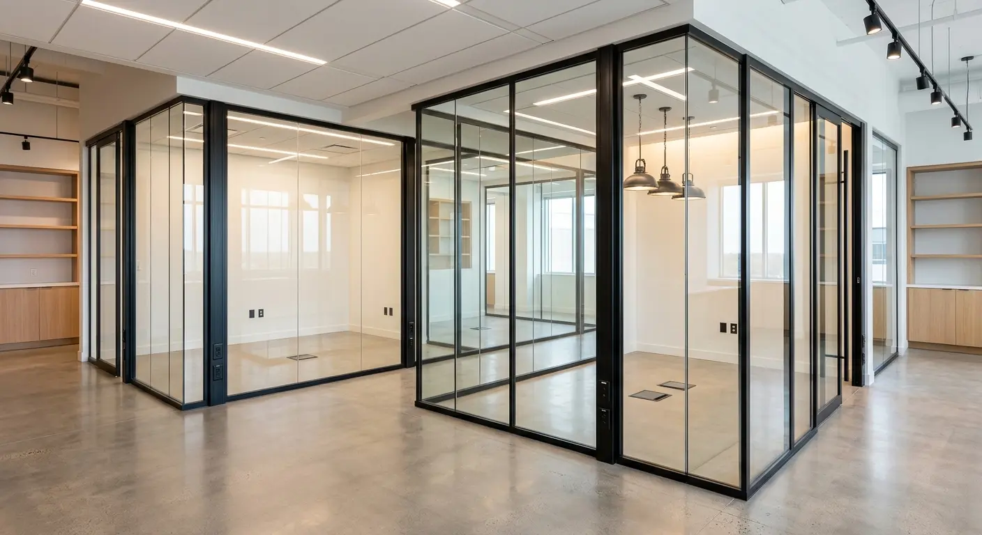
Power and data in partition walls is one of the fitout decisions that gets settled at rough-in and lived with for the rest of the lease. The cabling inside the partition cavity, the outlet positions on the wall face, and the way cabling enters and exits the partition all shape how each room actually works once people move in. Done well, the room reads as considered, with services where they are needed and out of sight elsewhere. Done badly, the room ends up with surface-mounted conduit, extension leads across the floor, and daisy-chained power boards under desks because the original installation did not anticipate where the equipment actually sits.
The pattern that fails treats cabling as the electrical contractor’s responsibility separate from the partition install. The two trades do coordinate at rough-in, but the design decisions that drive both – outlet positions, cavity depth, penetration handling – need to be settled at fitout design stage. Where the design holds the answer, the trades execute cleanly; where the design leaves it to site coordination, the result depends on whichever trade gets there first.
Designing the outlet positions before the partition goes up
Outlet positions on the partition face should be plotted on the fitout drawings, not left to the electrician’s interpretation. Each room’s layout – where desks sit, where AV equipment mounts, where collaboration zones need power, where data points are needed – drives the outlet positions, and the outlet positions shape what goes inside the cavity.
Standard outlet provisions for a typical meeting room include power and data at the wall where any AV equipment mounts, power at the conference table position if floor boxes are not being used, power and data at any presenter or speaker positions, and provision for specialised equipment (video conferencing cameras, ceiling-mounted screens, integrated speakers). Standard provisions for a typical workstation zone include power and data at each desk position, with count and configuration matching the desk layout.
Under-designed outlet plans usually default to generic provision – two power and two data per wall, evenly spaced – that does not match the actual desk or equipment positions. The result is outlets in the wrong place for the room’s actual use, with extension leads and surface-mounted runs filling the gap. The fix is to plan outlet positions against the actual room layout, even before furniture is procured, because the outlets are in the wall for the lease’s full term.
What goes inside the partition cavity
The partition cavity (the space inside the framing between the wall faces) accommodates the cabling that connects the outlets to the building’s power and data infrastructure. For plasterboard partitions, the cavity is typically 90 to 150 millimetres deep depending on the framing depth, with cabling running vertically along studs or horizontally between fixed points. For glass partitions, the cavity is minimal or absent, with cabling running externally to the partition or in floor or ceiling routes.
Plasterboard partition cavity design needs to accommodate the cable count, the cable types (separated for power, data, and any low-voltage systems to manage interference), the fastening points where cables attach to the framing, and any provision for future cable additions. A cavity packed tight at install with no spare capacity becomes a problem when the tenant needs an additional run mid-lease; the existing cables have to be moved, or the wall has to be opened, neither of which is cheap.
The acoustic implication of cabling in the cavity is the part most under-considered. A partition with significant cable routing has less room for acoustic insulation, and the cables themselves can transmit sound through the cavity if they share routes with insulation. For acoustic-rated partitions, the cable routing needs to be planned so it does not compromise the insulation pattern. Acoustic insulation choices have to coordinate with cabling routes rather than be specified in isolation.
Penetrations through the partition
Cables that enter or exit the partition cross the wall surface through penetrations. Each penetration is a potential acoustic weak point if not detailed properly, a potential fire-compartment breach if the partition is fire-rated, and a potential point of damage if the cable handling is not protected.
For acoustic-rated partitions, penetrations should be sealed acoustically: rubber grommets at outlet boxes, acoustic putty pads behind outlets, sealed conduit at any larger penetrations. A partition specified at STC 45 with unsealed outlet penetrations performs at STC 30 to 35 in practice, because the sound finds the path of least resistance through the penetrations regardless of the partition’s nominal rating.
For fire-rated partitions, penetrations have to maintain the fire rating. Approved penetration sealants, fire-rated putty pads, and intumescent collars at any conduit penetrations all contribute to the rated assembly. The penetration details should be specified on the drawings rather than left to site discretion; unrated penetrations through a rated partition compromise the rating, and the building certifier or fire engineer may require remediation.
Back-to-back outlet boxes (where outlets sit directly opposite each other on the two faces of the same partition) are an acoustic and fire-rated weak point because the outlet box itself becomes a partial penetration through the wall. The fix is to offset back-to-back outlets by at least 600 millimetres horizontally, or to use sealed back-boxes that maintain the partition’s rating across the penetration.
Coordinating with floor and ceiling routes
The cabling that enters the partition has to come from somewhere – usually a floor route, a ceiling void, or an adjacent partition. The coordination between the partition cavity and these routes determines whether the cabling delivery is clean or whether it ends up surface-mounted.
Floor routes (cabling in floor boxes, raised floor cavities, or floor channels) deliver cabling to the partition’s base, with the cabling rising vertically inside the cavity to the outlet positions. The floor route is usually the cleanest option for workstation zones where desks sit close to the partition. The coordination needs the floor box positions aligned with the partition’s base, and the cable count sized for the partition’s outlet count plus any future allowance.
Ceiling routes (cabling in the ceiling void, dropping down into the partition cavity at specific points) deliver cabling from above. The coordination needs the drop points planned, with the partition framing accommodating the drops and the ceiling junction sealed where the cables enter. Where ceiling drops are under-coordinated, the cables enter the partition through whatever point happens to be convenient, with the cavity routing inefficient and the acoustic seal at the junction compromised.
Adjacent partitions (cabling running horizontally between rooms through shared cavities) works for some layouts but creates dependencies between rooms. A cable run through three adjacent partitions to reach the fourth means modifications to any of the three involve cable disruption. The cleaner pattern is to source each room’s cabling from a floor or ceiling route at the room level rather than thread through adjacent partitions.
Power and data on glass partitions
Glass partitions present specific challenges for power and data integration because the cavity is minimal or absent. The cabling cannot run inside the partition the way it can in plasterboard, and outlets typically cannot be mounted in the glass panel itself. Glass partition systems handle services around the partition rather than through it, and the design has to plan the route in advance.
The standard approach for glass partition zones is to run cabling in floor routes (floor boxes positioned to serve the room’s equipment), in ceiling routes (cable trays or ducts running parallel to the glass partition with drops at specific service points), or in dedicated channels attached to the partition framing (visible aluminium or steel channels with cables inside, sometimes accepted as part of the visual language).
For meeting rooms with glass walls, the AV provision typically comes through a solid section of wall (often a plasterboard panel within the otherwise-glass enclosure) or through a freestanding rack within the room. The solid section accommodates the screen mount, the cable terminations, and the AV equipment connections. Pure-glass meeting rooms without a solid section often end up with portable AV setups that work but lack the integration of fixed installations.
Under-planned glass partition zones commonly end up with cabling that surfaces visibly because the original design did not allocate floor or ceiling routes. The fix at install stage usually involves surface-mounted aluminium channels, which work but compromise the clean reading of the glass partition. Planning the cabling routes at design stage avoids the issue.
Future-proofing the installation
Power and data requirements evolve through the lease. Devices that did not exist when the original fitout was specified appear and need provision. Workstations that handled two monitors and a phone may need to handle four monitors, multiple device chargers, and high-bandwidth data. Meeting rooms that handled occasional video calls may need to handle daily hybrid meetings with multiple integrated devices.
The decisions that support future-proofing are conduit capacity (oversized conduit runs that accommodate cable additions without rework), outlet count headroom (one or two more outlets than current need, in positions where future devices would plausibly sit), data cable specification (Cat 6A or higher rather than minimum Cat 5e, to support future bandwidth requirements), and accessible cable routes (floor boxes and ceiling drops that can be reached for modification without major demolition).
The cost of future-proofing at install is small relative to the cost of retrofitting mid-lease. Adding one extra conduit run at install costs a fraction of opening the wall to add the same conduit two years later. Tenants who skip future-proofing typically end up with mid-lease cabling work running through ceiling voids and along partition surfaces, and the workplace visibly shows the limitations of the original spec.
Specifying the integration before rough-in
The cleanest brief for power and data integration into partition walls identifies the outlet count and positions per room (mapped against the planned furniture and equipment layout), the cabling specification (cable type, conduit capacity, future-allowance), the routing strategy (floor, ceiling, or adjacent partition), and the acoustic and fire-rating requirements for any penetrations.
With the brief at that level of detail, the electrical and partition contractors coordinate cleanly. Without it, the integration defaults to whatever the trades work out on site, which usually delivers a functional installation but not one optimised for the room’s actual use.
Happy to walk through the integration spec alongside the partition design before procurement runs – the cabling routing, cavity capacity, and penetration detailing are usually quicker to resolve as one conversation than as separate trade discussions.
📞 Call us on 1300 60 93 93