
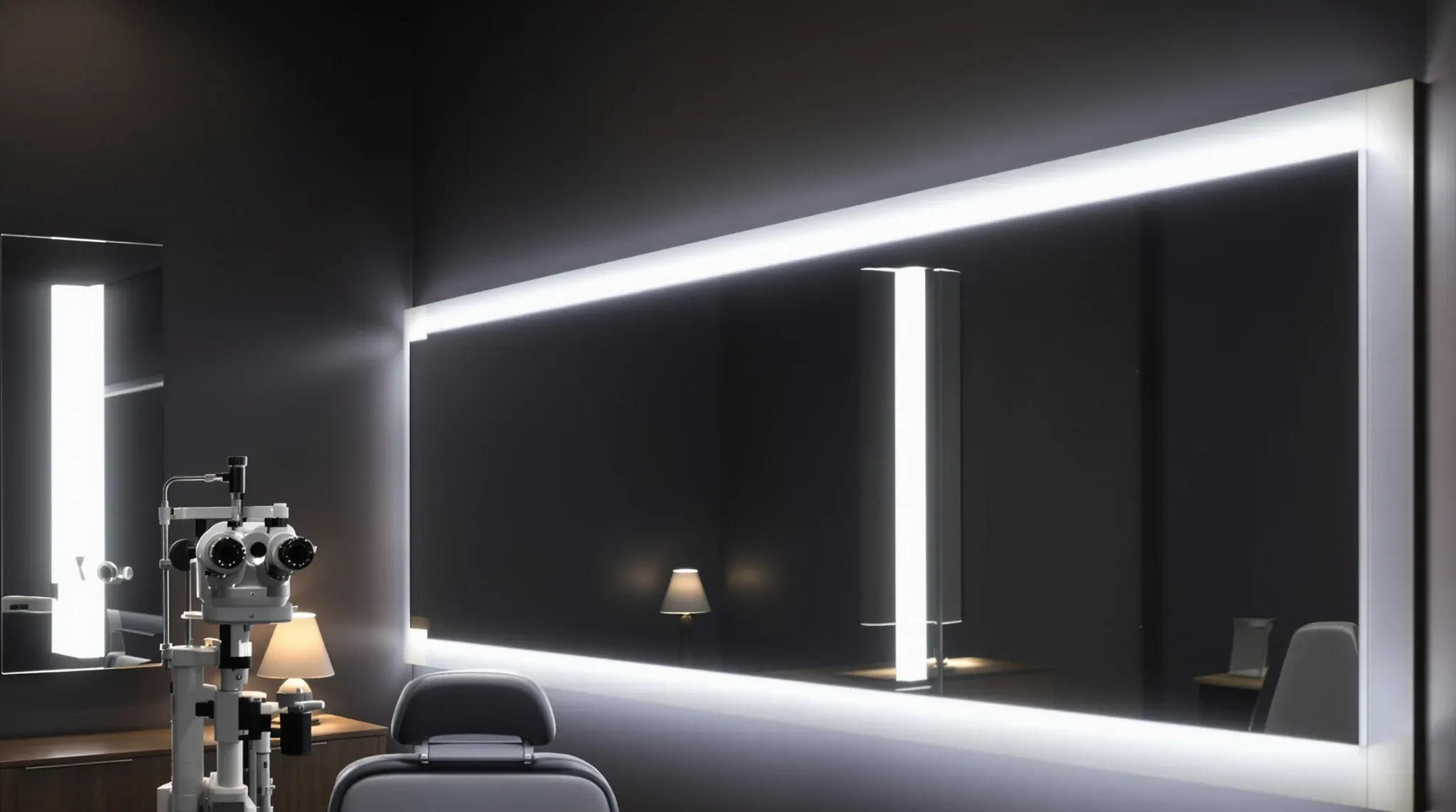
An optometry practice is two tenancies built as one. The front is a shop: a bright dispensing floor, fitting tables and mirrors, designed so frames look their true colour. The back is a set of clinical rooms that need a fixed testing distance, lighting that can be taken down to near dark, and dedicated power and data for diagnostic instruments. Those two halves want opposite conditions, and they usually sit a few metres apart in a narrow shop or suite.
When we price an optometry fitout, the drawing is set out from the testing room first. The length of the testing lane, the mirror wall, the light control and the equipment services decide where every other wall goes. The retail floor then takes the space that is left at the front, and the job becomes keeping its light and activity out of the rooms behind it.
Planning the Floor Around the Testing Distance
Distance vision has traditionally been tested at 6 metres, and a full-length refraction room can support that directly. Very few strip shops or centre tenancies give a practice a 6 metre room plus a patient chair and circulation behind it, so most practices fold the distance with a mirror: the chart sits behind or above the patient and is read in a mirror on the opposite wall, which doubles the path. The other option is a chart scaled for a shorter distance, such as a 3 metre chart, which suppliers note can suit many clinics when the scale is checked. Some compact chart systems are designed to deliver a 6 metre test in a much smaller room.
Each of these gives a different room length, and the optometrist and equipment supplier choose between them. For the build, the number that matters is the clear internal dimension once walls are lined. Plasterboard, framing and any acoustic lining all take depth off the slab dimension, so a room drawn to the centreline of its walls can come up short of the supplier's figure.
In a deep, narrow shop the testing lane usually runs front to back along the tenancy, with pre-test and imaging rooms beside it and the dispensing floor facing the street. We confirm the supplier's required clear length, chart position and mirror position before anything else is drawn, then lock the walls around that dimension.
Building the Chart and Mirror Wall
The mirror wall and the chart wall need tighter setout than any other walls in the practice. A large mirror needs a flat, rigid substrate to avoid distortion, which usually means extra studs and a continuous backing sheet or noggins behind the lining at the height the mirror will sit. The chart wall may carry a wall-mounted screen or projector bracket, and that load needs steel backing or timber noggins built into the framing before the plasterboard goes on.
Both walls also need services in exact positions. A digital chart or screen needs power and a data point behind or beside its bracket, and the patient chair and instrument stand usually need power close to their base. Those positions come from the supplier's installation drawing, and a floor or wall outlet set out even a short distance from the chair's footprint can end up under the base or leave a lead across the floor.
The sight line between the patient, the mirror and the chart has to stay clear. Doors, downlights and exit signs are kept off that line, and the door is usually placed on a side wall rather than the end walls. We set out the chair, mirror and chart positions on the slab at the start of framing so they can be checked against the drawing while the walls are still open.
Light Control and Blackout in the Clinical Rooms
Slit lamp examinations are typically done with the room lights dimmed, and equipment suppliers list lighting control as a planning item for imaging rooms. That makes light control a building task, and it works at three levels: stopping outside light getting in, dimming the room's own lighting smoothly, and keeping small task lights available while the main lights are down.
Stopping light getting in is mostly about the envelope of each room. Testing rooms are usually planned without external windows, and any window that cannot be avoided takes a blackout blind in a closed head box or a fixed opaque panel. Doors are solid rather than glazed, with perimeter seals and a threshold seal or drop seal where the gap under the door would otherwise let a strip of retail lighting across the floor. Gaps around ceiling tiles, downlight trims and service penetrations also leak light from a bright ceiling void, so a set plasterboard ceiling or a sealed tile layout suits these rooms better than an open grid.
Dimming depends on the lamp, the driver and the dimmer working together. LED fittings paired with an incompatible dimmer can flicker or fail to dim fully, so we match the dimmer to the fitting manufacturer's compatibility listing when the lighting is selected rather than on site. Switching is placed where the optometrist can reach it from the chair, with the task lighting on a separate circuit from the main lights. Emergency and exit lighting still has to meet the building's requirements, so its position is coordinated to sit outside the patient's view of the chart.
Pre-Test and Imaging Rooms: Power, Data and Heat
Pre-test and imaging rooms hold the practice's diagnostic instruments: auto-refractors, retinal cameras, OCT units and visual field analysers. Equipment suppliers list power access, network access, operator space, stable flooring and clearance around each device as planning items, along with service access for technicians once everything is installed. Each of those turns into a detail on the electrical and partition drawings.
On power, each instrument generally takes its own outlet at bench or table height, with spare outlets for the screen and computer that run it. Extension leads and power boards are not a good substitute, and at least one field analyser service guide advises against extension cords and specifies a particular power table. On data, each networked instrument needs a point that runs back to the practice's comms cabinet so images and results reach the practice software. We fix these positions during first fix, because coordinating electrical with partition installation is far simpler while the studs are exposed.
Heat is easy to overlook. The same field analyser service guide lists a heat output of around 460 watts for one unit, and a small room holding two or three instruments, a computer and a person with the door closed can warm up quickly. That usually means a supply air outlet and a return path for the room, run through the ceiling service zone alongside the lighting, data and sprinkler work already competing for space above a clinic. The field analyser guide also calls for a stable, vibration-free surface, so the table or bench under each instrument needs a solid, level floor beneath it.
The Dispensing and Fitting Area
The retail floor needs close to the opposite lighting of the testing rooms. An optometry business publication recommends neutral white light around 4000K with a colour rendering index of 90 or higher, so frame colours show accurately, and notes that dispensaries are commonly under-lit. Higher ceilings need higher lumen output for the same result. Fitting mirrors work best with a directional downlight placed close to the mirror and angled onto the customer, which avoids shadows across the face. Dispensing tables and the reception counter need their own overhead or pendant lighting so the work done at them is not in shadow.
The build scope here is the lighting layout, the ceiling, the power and data at the dispensing and reception desks, and the wall backing for mirrors. Frame display joinery sits outside the build scope and is usually supplied by a specialist, but its power and lighting positions need to be in our electrical drawings before the ceiling is closed.
If lenses will be edged in the practice, the workshop needs planning early. Wet edgers either run on a direct water supply and drain, which needs plumbing to the bench, or on a recirculating tank and pump that sits under the counter. The bench has to carry the equipment weight, and cutting some lens materials gives off a strong odour, so the workshop usually needs extraction and a location away from the testing rooms.
Where Glass Meets the Clinical Rooms
Glass is the natural material for the front of the practice, and it becomes a problem as soon as it reaches the clinical rooms. A bright dispensing floor behind a glazed wall, a highlight window or a door vision panel sends light straight into a room that has to go dark. The pattern that works is one many medical fitouts follow: glass only in circulation areas such as the waiting area and corridor, with solid walls around the rooms where examinations happen.
Pre-test rooms are the exception some practices ask for, so staff can see into the room from the front counter. A glazed front can work there if the instruments in that room tolerate ambient light. Where that glazing is built, it takes a frosted film band or an internal blind, and the practice accepts that the room cannot be made fully dark. We confirm with the optometrist which instruments go in which room before any glazing is ordered, because moving an imaging device into a glazed room after handover leaves a light problem that film alone does not fix.
Acoustic privacy between consulting rooms and the retail floor follows the same approach as any other clinical suite. Walls to the testing rooms run up to the slab or are closed off above the ceiling, and doors take acoustic seals, which also helps with light.
Hold Points Before the Walls Are Closed
Most of the precise work in an optometry fitout is locked in once the plasterboard is on, so we build in a small number of checks before the walls and ceilings are closed. The equipment supplier's installation drawings are needed before framing starts, and equipment delivery is aligned with the joinery, flooring, electrical and network work so instruments arrive into a finished room.
- After framing, the clear length of each testing room is measured against the supplier's figure, allowing for the lining thickness still to come.
- Before lining, the backing for the mirror, chart and any screen brackets is checked in place, along with the height of every outlet and data point.
- Before the ceiling is closed, air supply to the pre-test and imaging rooms, dimmer wiring and any light-leaking penetrations are checked.
- After painting and flooring, the mirror goes in last so it is not damaged or dusted during finishes.
Within a complete office fitout these hold points sit inside the normal programme. Missing one usually means cutting open a finished wall in a room that has to be precise.
We set out the testing lane, mirror wall and chair position on the slab from the equipment supplier's drawings before the first stud goes up, then build the blackout, dimming and instrument services around that fixed dimension.
📞 Call us on 1300 60 93 93